Once upon a time, when race car chassis were rudimentary things and suspensions were rock hard drivers were given a very hard time. This is what Mike Hawthorn had to say about the Riley on which he cut his racing teeth.
“This was my first season and also my only one on pre-war cars with hard cart springs, but it made me realise why the drivers of the previous generation wore wide, stiffened body belts like corsets. They just had to do it to keep their insides in place. I did not realise it at the time and I took an awful shaking at Dundrod. I did not feel too bad at the time but the next evening I suddenly passed out and had to go to bed with whiskey and hot milk. My interior organs were in revolt against being thrown about like a stone bouncing down a tin roof.”
With such a car the suspension is not doing much suspending at all. In addition the chassis were not all that stiff, either in bending or on torsion, so the chassis itself ended up doing a lot of the dynamic stuff that should have been handled by the suspension. A bit like a go-kart chassis does today.
Why Bother?
Since Mike’s day the emphasis has changed from “stiff springing – soft chassis” to “stiff chassis – soft suspension”. The design emphasis is now on torsional stiffness. That is if you wind the chassis up, how much does it twist. A chassis that does not twist at all lets the suspension do its stuff with the promise of full weight transfer “tunability”. One that twists, even just a little bit, job shares with the suspension. So the question is how stiff is stiff enough?
The reason for even asking the question is that a torsionally stiff chassis enables us to indulge in the practice of “chassis tuning”. Back in the 50’s such fun and games were almost unheard of. Successful cars were built by people with a prior history of producing successful cars. The cars had to be good straight out the box, and if they weren’t there was not much that could be done about it.
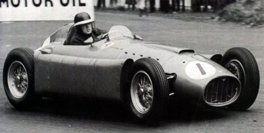
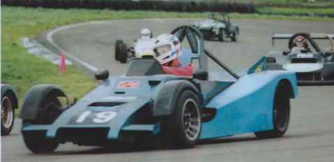
The photo shows Mike Hawthorn in a Lancia Ferrari. He comments “The car under steered badly on sharp corners; if I got the tail sliding under power to help it round then lifted my foot to control it, the rear came back rather viciously and tried to whip around the other way. Yet on fast corners it drifted nicely with all four wheels.” The driver had to adapt his driving style to suit the limitations of the car.
A torsionally stiff chassis provides a way of doing something about this. When a car goes around a corner it generates a side load, and that side load results in weight transfer from the inside to the outside wheels. Too much transfer at one end or the other and the tyres at that end lose their ability to handle the cornering loads. Push it hard enough and you will be sliding instead of driving. A “tunable” chassis lets you play games with the distribution of the weight transfers. Simply put it allows you to re-balance the car. That is you can adapt the car to suit the driver.
Some Basic Considerations.
If you have a copy of my “The Art of the Special” book you will find a whole chapter dedicated to just
what the effects of changing roll stiffness at one end of the car or the other can have on the distribution of weight transfer. What the mathematics in that chapter don’t say is that the analysis assumes that the chassis is infinitely stiff in torsion. That is an input at one end of the car will show up in all its glory at the other end. Real life is of course not so simple.
All chassis’ will twist if you try hard enough. When they do so they become part of the “suspension” of the car. The chassis is in effect a further torsional spring attached to the real springs at each corner of the car. Loads and deflections will be shared between the springs and the chassis, and the softest part of the system will absorb the greater part of the total deflection. The weight on any wheel is determined by the deflection of the spring at that wheel. Deflection taken up in twisting the chassis is not available to compress the spring, so not all of those lovely calculated weight transfers hinted at in “The Art of the Special” will necessarily show up where the rubber hits the road.
To be fair, it doesn’t need to. A “tunable” chassis will still respond to partial weight transfers, just not as sharply as if it got the whole lot. So how much is enough?
Some What to Look For Guff.
Most of this stuff goes on in secret in the back rooms of the car designers, but the Formula SAE boys are not afraid of publishing their musings. A very good discussion on how much torsional stiffness is enough is found in the Leeds University paper SAE 2000-01-3554 “The Effect of Chassis Stiffness on Race Car Handling Balance”. Simplifying and paraphrasing the authors conclusions, if the chassis torsional stiffness is at least equal to the total suspension roll stiffness of the car, then a reasonably tunable combination will result. Their criteria for reasonableness is that at least 80% of the calculated weight transfer will turn up at the wheels.
We can turn this finding on its head and say that if your chassis is only half a stiff as the suspension then you will get 60% or so efficiency in weight transfer tuning, or if you want 90% efficiency then the chassis stiffness needs to be at least double the roll stiffness, and so on. The Leeds paper also provides a table “Tyres Suspension and Handling” (Cambridge University Press: J.C. Dixon)giving some sample suspension roll stiffness for different car types as of 1991. (I have added an imperial units column for direct comparison with “The Art of the Special” data)
| Car Type | Total Roll Stiffness (Nm/deg) (ft-lb/deg) |
| Saloon | 300 – 800 (200 – 600) |
| Sports Car | 2000 (1500) |
| Sports Prototype | 18,000 (13,000) |
| Formula One | 20 – 25,000 (15 – 18,500) |
| Formula SAE | 500 – 1500 (400 – 1,100) |
The suspension roll stiffness calculation for K9 was in the order of 4,500 ft-lb/degree of roll. This being a pretty typical “clubmans” type car it sits properly between the road going sports car and the sports prototype figures given in the table.
K9 responded very nicely to small changes in roll bar settings. To get there we neither calculated chassis stiffness beforehand nor tested for it after. Instead we relied on rules of thumb from that master of the space-frame, Frank Costin. “If any two torsionally stable systems were pin-jointed together at any two node points torsional continuity would exist.” (Competition Car Chassis Design: Automotive Engineer article December 1983.)
Testing, Testing.
If we had tested what would we have found? A loaded question, if you will pardon the pun. That would depend on how we tested it. The simplest and the most old fashioned way would have been to tie the back of the bare chassis onto something solid, support one corner of the front end on something similarly solid and tweak the unsupported end with a big bar while armed with a load cell and a dial gauge. A bit like below.
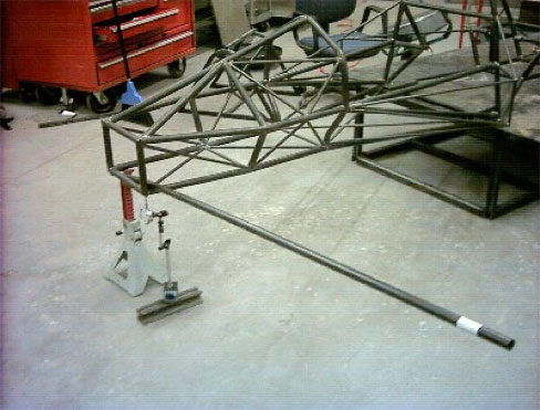
We would get a result for sure, but it might not mean much. The chassis in this simple test is not being loaded in the same way as it would be on the track. The loads are not being applied at the suspension mounts, which are the bits we are supposed to be matching up to. We could improve things by anchoring to the spring hanger mounts at the rear and one front corner, and loading the front bar across the front suspension hanger mounts. But a basic flaw would remain. When you tweak up the bar you are not only loading the chassis, but also the anchorage system and the tweak bar itself. How do you know which bit it is that you are testing? The anchorage system has to be infinitely stiff to give accurate results and nothing is infinitely stiff.
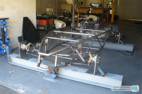
The next shot shows a kit car undergoing an official Australian Design Rule compliance test. The test rig has big strong beams front and rear. The front one is able to pivot and the back one is fixed firmly to the floor. The loads are being applied “hub to hub” by using anchor plates to tie the hubs to the beams, and then forcing a pivot angle onto the front beam. The test is done with the suspension linkages in place but with the springs replaced by rods of a fixed length.
Even so the purists still quibble that the pivot point below the front centre of the chassis creates an artificial load pattern and that the car will still be loaded differently on the track.
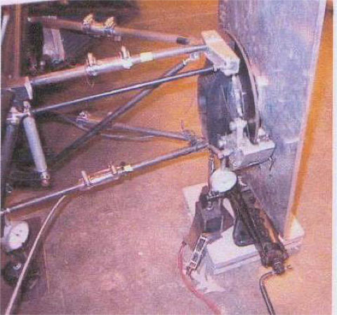
An alternative test by one wheel bump is recommend in the Cornell University paper SAE 2002-01-3300 “Design Analysis and Testing of a Formula SAE Car Chassis.” Originally this was seen as a fall back from the need to make a complex test rig, but it is also more representative of the real loadings on the track. Its down side is that the maths are a bit more complex. You will need at least one corner weight scale, a scissor jack, a number of dial gauges, some dummy steel blocks the same height of the closed scissor jack (or of the jack/corner weight scale combination), a set of camber plates and some way of tying down at least two of the other corners of the car. The photo shows the set up at the corner to be loaded. The wheels come off the car and the spring/dampers units are replaced by fixed length rods. The corner weight scale goes on the floor, with the closed scissor jack above it. Identical camber plates go on all four corners of the car and the dummy blocks go under the other three “wheels”.
At least two non test corners need to be anchored down. If you are doing the single wheel lift at the front left corner then the two corners that must be anchored down are the front right and its diagonal partner the left rear. The other rear corner will end up with a downward force on it so strictly speaking it does not need to be nailed down. Dial gauges are placed at the test wheel hub, so you can see how much tweaking you have done, and under the bottom rails of the chassis at each corner of the car, so you can work out the total twist of the chassis. Ease up the scissor jack one or two millimeters at at a time (the Cornell boys went up to about 10mm of tweak). Record the weight on the scale and the readings on all of the dial gauges for each test point. Graph the results, do the maths and get your answer.
Finite Element Modeling. All this testing, you say. What happened to good old mathematical modeling? The Formula SAE boys in fact do both. They all report that what comes out of their finite element models does not match the actual test results. Typically about 2/3rds of the modeled stiffness actually shows up under test. There are causes for error in both. Even the fanciest testing includes bits and pieces that properly belong in the suspension calculations. (A property called “installation stiffness” covers the taking up of slack in suspension joints, the squeezing up of any elastic bushes and so on). So neither test nor model is perfect. The Cornell authors remind us that while the process of solving finite element problems is a science, the creation of a model by which to apply the process is an art. The model can never include all of the stuff that influences the test results, so it is an approximation of the real thing. In practice the testing is used to calibrate the model. The model puts you in right paddock and the testing tells you more or less where you are standing within that paddock. Looking at it just from the point of view of the chassis you could say that the mathematical model gives over realistic expectations of the finished article, and the test, if anything, under scores the actual chassis stiffness. Putting all the ideas together leaves the thought that having settled upon a target stiffness for the chassis as built, multiply it up by a factor of 1.5 or so to set a dummy target for the FEM modeling games.