Preamble:
When I was a lad, just beginning to muck about with car stuff, ladder frames were off the radar. The popular wisdom was that they were heavy, structurally inefficient and not good at handling torsional (twisting) loads. These days I am not so sure that all that need necessarily be so. I had occasion, a while back, to do strength calculations on a redesigned replacement chassis for a re-engined ’54 Corvette. That exercise got me thinking. This car was not intended for the Australian market but its heavy platform type chassis calculated out as exceeding the ADR torsional stiffness rules for “one off” cars. The question I now ask myself was could that conclusion also hold true also for a traditional, lighter ladder frame, say for a retrospective special, while still remaining in period? (The ADR requirement is/was 4,000 N-m/3,000 ft-lb per degree).
Why Tube Frame Ladders?
Once upon a time car chassis were smaller versions of today’s truck frames. Big open channels each side, cross members in handy places, and beam axles front and rear. These chassis don’t need torsional stiffness as their axle beams will always present the tyres to the road surface at the same angle no matter what the chassis is doing. There was no pressing need to change this architecture for racing cars until independent suspension came into common usage.
Design Examples
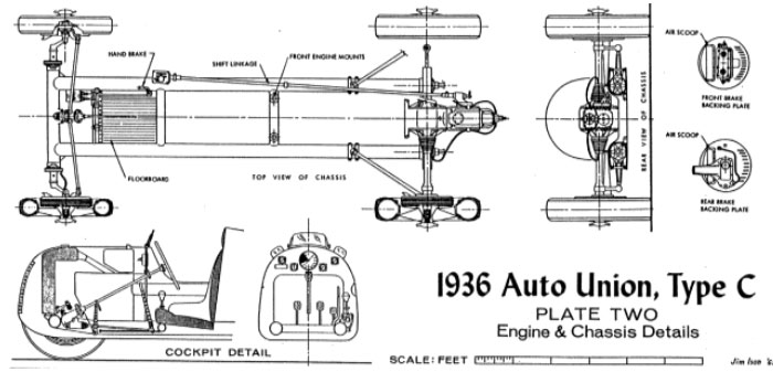
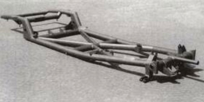
That revolution arrived with the 1934 Mercedes and Auto Union racers. When the wheel to road alignment is determined by the attachments to the chassis frame rather than by a solid axle beam a whippy chassis becomes a liability. A closed tube is many times stiffer in torsion than is an open channel, so the distinctly different Mercedes and Auto Unions (front engine versus rear engine) shared a common factor. They both had round tube ladder chassis. The 1936 Auto Union is shown above. It is really just a big go-kart except its main frame members are 100mm tubes 2.5mm thick. This frame calculates out at having around 2,000 ft-lbs per degree of torsional stiffness.
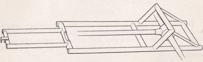
Translating this into a typical ‘50s sport car lost most of that stiffness. The frame for the 1951 Tojeiro MG, (that eventually morphed into the AC Cobra), is shown in the next picture. It is a scaled down crib of the Auto Union, but with bits hanging off the sides to support the bodywork. The seats are mounted above the tubes. The Tojo was made from 3 inch x 1/16 inch tube on a 90 inch wheelbase. The smaller tubes greatly affect the stiffness of the chassis, dropping it to about 600 ft-lbs per degree.
Widening such a chassis out marginally increases the torsional resistance of the frame while also allowing for lowering the seating position. The 1955 Lister Bristol frame below illustrates the transition. This variation calculates out at about 700 ft-lb per degree.
Improvements
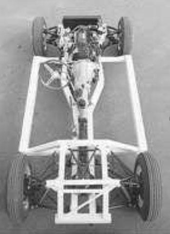
A logical step is to amalgamate the two ideas by using a central spine to contain the mechanical bits and adding in an outer tube run. The seats remain low mounted. The later series Elva Courier on the left illustrates this approach. The Elva calculates out at 1500 ft-lb per degree, half way to the target, but at the expense of more or less doubling the chassis weight.
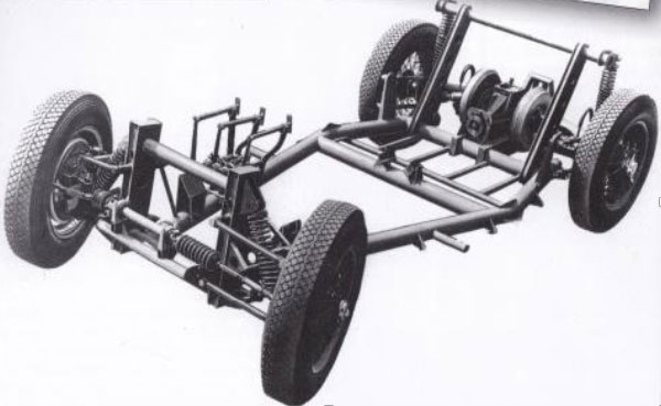
Alternatively we could use diagonals in a wide bay chassis. This typically 50’s Italian approach is illustrated on an early 50’s Alfa Romeo chassis. (For best results the diagonals need to be at 45 degrees to the frames side members).
Sticking with our 3 inch tubes the Alfa frame gives a calculated stiffness of approaching 2000 ft-lb per degree. A little better than the double run frame of the Elva with much the same weight penalty.
Where to Next?
The problem with all of these “fixes” is that they leave a relatively slender un-braced engine bay at the front of the chassis, and the bulk of the total chassis twist occurs here, so this is the area that needs the most attention.
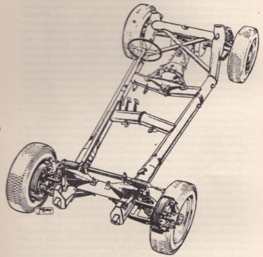
A starting point could be a typical 50’s Ford 10 Special. (The “wheelbarrow” arms on the front of these frames were there to allow radius arm mounts with reasonable geometry when the original Ford beam axle was converted to swing axle independent form). If we went to wishbone suspension we could build a braced frontal bridge similar to the rear one. If these bridges are then “triangulated” into a set of 3D rigid tetrahedronal structures then the end bays can become very stiff indeed. Also if we include a diagonal brace with optimal geometry in the mid part of the frame then the diagonals don’t need to be the same depth as the main rails. They don’t even need to be tubes. With care we can more than double the torsional resistance of the centre bay in the sketch above with only a modest weight penalty.
In brief we shuffle the Ford 10 Special around by splaying the wheelbarrow arms out to join the main run of the outer tubes, add tetrahedron structures at each end and diagonally brace the remaining flat area in the middle. We could end up with about 3,500 ft-lb per degree. Top it off with a set of Lynx body moulds and our retro special is ready to rumble.
Going Large:
Off course we don’t necessarily need to stick with 3 inch steel tubes. The makers of the 1952 ERA G type used big diameter thick wall magnesium tubes and claimed 3,300 ft-lb per degree for the resulting frame.
Or adopt an intriguing interpretation of the SAE Formula Student rules.
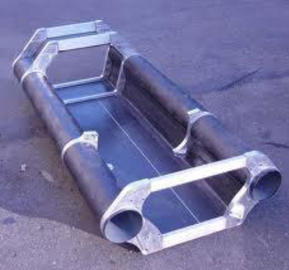
These cars are normally built as a space frame chassis typically giving 1,000 -1,500 ft-lb per degree. This one is definitely tubular but it is just as definitely not a space frame. It is a more like a monocoque. The tubes are in 6 inch diameter carbon fibre and the bridges are aluminium castings.
This brings us full circle back to the Auto Union, two big tubes bridged at each end. A variation of this in steel and longer and in a wider sports car form promises 4,000 ft-lb per degree with a similar weight to the Elva.
An interesting thought, is it not, that twin tube chassis ideas lead us logically to monocoques, not to space frames.